In gas heat exchanger systems, the flow configuration — particularly counter‑flow design — plays a pivotal role in determining overall thermal performance and energy efficiency. When transferring heat between two gaseous streams (e.g., hot flue gas and cooler inlet air), the direction in which the fluids travel relative to each other can dramatically impact heat recovery performance. Counter‑flow arrangements — where hot and cold gases flow in opposite directions — maintain a favorable temperature gradient over the full length of the exchanger, enabling higher thermal efficiency and reduced heat losses when compared with alternative configurations like parallel or cross flow. These characteristics make counter‑flow designs especially valuable for industrial heat recovery systems, including compact plate heat exchangers and larger recuperator systems.
This article explores the benefits of counter‑flow design in gas heat exchangers, explaining core principles, comparative performance data, engineering advantages, industry applications, design considerations, and how counter‑flow systems help maximize heat recovery efficiency. Additionally, we’ll highlight advanced solutions such as the Gas‑to‑Gas Platular Heat Exchanger to illustrate practical implementations of counter‑flow principles.
Key Takeaways
Counter‑flow design maximizes heat transfer efficiency in gas heat exchangers by maintaining a high temperature difference across the exchanger length and reducing thermal stress.
Counter‑flow arrangements often deliver higher heat transfer coefficients, enabling smaller, more cost‑effective designs while achieving superior energy recovery.
Compared to parallel or cross‑flow configurations, counter‑flow systems offer improved outlet temperature control, reduced exergy loss, and better suitability for industrial heat recovery tasks such as flue gas recuperation.
Practical applications include industrial heat recovery, HVAC systems, petrochemical processing, and power generation, where optimizing thermal performance is essential.
What Is Counter‑Flow Design in Heat Exchangers?
A counter‑flow heat exchanger is a configuration where two fluids — in this context, two gas streams — move opposite each other within the exchanger. The hot gas flows in one direction, while the cold gas flows in the opposite direction, allowing the coolest portion of the cold stream to interact with the coolest portion of the hot stream, and similarly at the other end.
This arrangement contrasts with:
Parallel flow, where both fluids travel in the same direction — leading to reduced temperature gradients and lower efficiency.
Cross‑flow, where fluids move perpendicular to each other — often used in specialized ventilation equipment but typically less efficient thermally than counter‑flow for heat recovery.
In counter‑flow configurations, the temperature gradient between the hot and cold fluids is maintained along the full exchanger length, enhancing heat transfer potential compared with other flow patterns.
Why Counter‑Flow Is More Efficient
The fundamental reason counter‑flow heat exchangers are more efficient lies in the temperature gradient maintained across the heat transfer surface. In a counter‑flow setup:
The hot stream cools gradually from one end to the other.
The cold stream warms gradually in the opposite direction.
As a result, the log mean temperature difference (LMTD) — a key driver of heat transfer performance — remains high throughout the exchanger.
Temperature Gradient Example
| Configuration |
Temperature Gradient Behavior |
Efficiency Trend |
| Counter‑flow |
Sustained high ΔT across length |
Higher efficiency |
| Parallel flow |
Rapid decrease in ΔT |
Lower efficiency |
| Cross‑flow |
Intermediate ΔT distribution |
Moderate efficiency |
This performance difference leads to multiple benefits:
Improved heat recovery, as more of the available thermal energy is transferred from the hot gas to the cold gas.
Reduced unit size for equivalent performance, saving space and capital cost.
Better control of outlet temperatures, useful in processes with strict thermal requirements.
Indeed, some studies and engineering reports suggest that counter‑flow arrangements can improve heat transfer performance by as much as 10–15 % compared to parallel flow designs under certain conditions.
Core Benefits of Counter‑Flow Design
Higher Overall Heat Transfer Efficiency
In counter‑flow configurations, the cold fluid meets the hottest part of the hot fluid at one end of the exchanger. This persistence of a significant temperature difference drives stronger heat transfer per unit surface area — improving the overall heat transfer coefficient.
Smaller Equipment Footprint
Because counter‑flow designs extract more heat for the same surface area, systems can be scaled smaller compared with parallel or cross‑flow designs while achieving comparable outlet temperatures — a crucial advantage when space and weight are constraints in industrial facilities.
Reduced Thermal Stress
In counter‑flow exchangers, temperature differences across the structure tend to change more evenly. This even temperature profile reduces localized thermal stress — helping extend the life of the exchanger and supporting more stable operation.
Enhanced Outlet Temperature Control
Counter‑flow arrangements can achieve a situation where the cold outlet approaches or, in theory, surpasses the hot inlet temperature — especially in counter‑current liquid systems and well‑designed gas systems — something that’s impossible in parallel flow configurations.
Broader Application Flexibility
Counter‑flow heat exchangers are applicable across:
Industrial heat recovery and waste heat utilization
Ventilation and HVAC systems
Petrochemical and power generation processes
Chemical and manufacturing systems requiring tight temperature control
Comparison: Counter‑Flow vs. Other Flow Patterns
Below is a detailed comparative analysis of counter‑flow relative to parallel and cross‑flow designs — focusing on efficiency, pressure drop, temperature approach, and practical considerations.
| Characteristic |
Counter‑Flow |
Parallel Flow |
Cross‑Flow |
| Heat Transfer Efficiency |
Highest |
Lower |
Moderate |
| Temperature Approach |
Smallest achievable difference |
Limited by same‑direction flows |
Intermediate |
| Thermal Stress |
Lower |
Higher |
Moderate |
| Compactness |
Excellent |
Moderate |
Moderate |
| Complexity of Flow Path |
High |
Low |
Moderate |
| Best Use Cases |
High efficiency heat recovery & tight temperature control |
Simple heat exchange needs |
Specialized applications |
Engineering Design Considerations
To fully benefit from a counter‑flow design, engineers must consider several key aspects:
Flow Channel Geometry
The geometry of flow channels influences velocity profiles and turbulence — both of which affect heat transfer rates. Optimized channels ensure balanced pressure drops while maintaining high ΔT across the exchanger.
Pressure Drop Management
While counter‑flow designs improve efficiency, they can induce higher pressure drops if channels are narrow or flow paths are complex. Balancing surface area with manageable pressure losses is critical.
Materials and Thermal Stress
Materials must withstand both high temperatures and repeated thermal cycling. Counter‑flow configurations, with their smoother temperature gradients, help reduce differential expansion stresses on materials.
Fouling and Maintenance
Industrial gases often carry particulates or contaminants. Design provisions that facilitate cleaning — such as accessible channel paths or removable elements — help sustain counter‑flow heat exchanger performance over time.
Real‑World Gas Heat Recovery Applications
Industrial Waste Heat Recovery
Counter‑flow configurations are ideal for waste gas heat recovery, where hot flue gases from furnaces or combustion processes exchange heat with incoming cleaning air or process gas streams — enabling significant energy reuse and cost savings.
HVAC and Ventilation Systems
In ventilation systems, counter‑flow plate heat exchangers recover heat from exhaust air to preheat incoming fresh air — improving energy efficiency in buildings and industrial facilities.
Chemical and Petrochemical
Processes that require precise thermal control — such as distillation or condensation — benefit from counter‑flow heat exchangers, which provide consistent and efficient temperature gradients.
Power Generation
Counter‑flow recuperators improve energy utilization in gas turbines and cogeneration systems by maximizing heat transfer between exhaust and intake streams.
Data‑Driven Efficiency Metrics
Consider a simplified performance comparison (illustrative) of a 1 m² heat transfer surface under different flow configurations for gas streams with identical inlet temperatures:
| Flow Configuration |
Estimated Heat Transfer (%) |
Efficiency Impact |
| Counter‑Flow |
100 (+) |
Baseline Reference |
| Parallel Flow |
~85 |
−15 % vs counter‑flow |
| Cross‑Flow |
~90 |
−10 % vs counter‑flow |
These percentage differences reflect typical trends seen in engineering comparisons where counter‑flow designs achieve higher effective heat recovery due to sustained temperature gradients across exchanger surfaces.
Key Benefits Summary
To summarize the primary benefits of counter‑flow design for gas heat exchangers:
Maximum heat recovery efficiency
Smaller equipment size for equivalent performance
Improved outlet temperature control
Lower thermal stress and longer service life
Flexible application across multiple industries
These advantages make counter‑flow the preferred choice in modern heat recovery designs — including advanced plate heat exchangers employed in industrial recycling of flue gases.
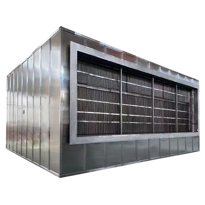
One example of cutting‑edge counter‑flow implementation is the Gas‑to‑Gas Platular Heat Exchanger, which integrates counter‑flow heat transfer in a compact, high‑performance unit engineered for industrial gas heat recovery.
FAQs
Q1: Why is counter‑flow more efficient than parallel flow in heat exchangers?
Counter‑flow maintains a higher temperature difference along the exchanger, resulting in a larger log mean temperature difference (LMTD) and more efficient heat transfer.
Q2: Can counter‑flow designs be used in plate heat exchangers for gas applications?
Yes — many plate heat exchangers incorporate counter‑flow paths, which help achieve excellent heat recovery performance in gas‑to‑gas heat exchange.
Q3: Does counter‑flow increase pressure drop in a system?
It can, depending on flow path complexity and channel geometry, but careful design balances pressure loss with the gains in heat transfer efficiency.
Q4: Are there flow patterns other than counter‑flow?
Yes — including parallel and cross‑flow, but counter‑flow generally offers the best efficiency for heat recovery applications.
Conclusion
Counter‑flow design stands out as one of the most effective configurations for gas heat exchangers, particularly when the goal is to maximize thermal efficiency, minimize heat losses, and achieve tighter temperature control between inlet and outlet streams. Its ability to maintain favorable temperature gradients and improve log mean temperature difference makes it a cornerstone of modern industrial heat recovery systems.
For applications where energy efficiency and heat recovery performance are critical, advanced solutions like the Gas‑to‑Gas Platular Heat Exchanger demonstrate how counter‑flow principles can be applied in robust, compact units — offering significant operational advantages across sectors such as manufacturing, chemical processing, power generation, and HVAC.


